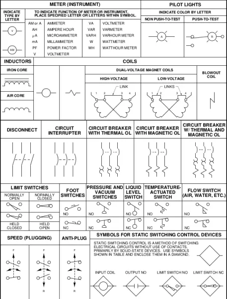
Industrial Electrical Symbols - Meter Symbols
Understanding electrical symbols is critical when wiring your industrial pumps to controllers, switches, machinery, or accessories. Failure to properly wire your centrifugal pumps or submersible pumps can damage the motor and significantly increases electrical shock or fire risk.
Our industrial electrical symbols guide helps you correctly identify components and prevent potential hazards during pump installation. Bookmark this page as a handy reference for future electrical projects. Safety first!
Have questions about how to install your pump? We always have customer services standing by. Contact us today.
Also, check out our electrical symbol guides for transformers and selectors below:

Partial Glossary for Metering Symbols
- Ammeter: Zero resistance device used to measure electrical current. Must be connected serially.
- Battery: Generates constant voltage and supplies electrical energy.
- Bell: An electric bell makes a single tone or repeated ringing sound when activated.
- Buzzer: Similar to an electric bell, an electric buzzer makes a constant buzz when activated.
- Capacitor: Stores electric charge. Can be used to filter or block DC signals while passing AC signals. Used with a resistor in a timing circuit.
- Circuit Breaker: Automatically operated electrical switch that protects electrical circuits from damage caused by short circuits or overloads
- Fuse: Sacrificial overcurrent protection device. This symbol represents low power/low voltage fuses.
- Ground: Connection to the actual ground or other “grounding” structure. Used to provide electrical shock protection and for zero potential reference.
- Inductor: Coil of wire that generates a magnetic field when an electrical current passes through it. Passive two-terminal electrical component used to store energy in the resulting magnetic field. Can also be used as a transducer to convert electrical energy into mechanical energy.
- Iron Core Inductor: Same as above, but with an iron core beneath the coiled wire.
- Resistor: Resistors restrict the flow of current. Used with a capacitor in a timing circuit.
- Voltmeter: Very high resistance device used to measure electrical voltage. Must be connected in parallel.
- Wattmeter: Device used to measure electric power.
Switch Types for Submersible and Centrifugal Pumps
Disconnect switches isolate electrical currents, allowing you to quickly cut power to your industrial pumps in emergencies or perform maintenance. These switches come in various input/output styles, including:- SPST (Single-Pole, Single-Throw): A simple switch with one input and one output. Switch will be either closed or completely disconnected. Requires only two terminals. Ideal for on/off switching.
- SPDT (Single-Pole, Double-Throw): A switch utilizing three terminals: one common pin, two pins vying for connection to the common (only one can be connected at a time). Ideal for selecting between two power sources or swapping inputs. Can be made into an SPST switch by simply leaving one of the throw pins unconnected.
- DPST (Double-Pole, Single-Throw): Essentially a doubled SPST. A switch with two inputs and two outputs; each input corresponds to one of the outputs. DPST switches provide versatility, as they can accept two inputs and drive two different outputs to the same circuit.
- DPDT (Double-Pole, Double-Throw): Essentially two SPDT switches, controlling two different circuits, and always switched on together from a single actuator. Require six terminals.
- NO (Normally Open): The “normal” state for a switch is its non-actuated position. Depending on its construction, a switch’s normal state can produce an open circuit or a short circuit. When open until actuated, a switch is a normally open (NO) switch; when activated, a NO switch closes the circuit.
- NC (Normally Closed): Essentially the “opposite” of an NO switch. A switch that creates a short circuit when not actuated. Normally closed (NC) switches create a short circuit when actuated.
If you still have questions about electrical symbols or how to wire your centrifugal or submersible pump, send us a message! Our knowledgeable team is here to answer all of your questions.


